Intel 8080 Emulator
An emulator for the Intel 8080 microprocessor from 1974. To demonstrate the 8080's capabilities, the hardware of a basic arcade cabinet is simulated as well, complete with a Space Invaders ROM.
Controls
Esc - Exit
C - Insert a coin
Q - Singleplayer start
E - Multiplayer start
A - Move left
D - Move right
S - Fire
The Intel 8080
Below is an image of the 8080 courtesy of Wikipedia. It was released in 1974 and subsequently used in early computers such as the Altair 8800. It was also used in several early arcade games, such as Space Invaders, which is the ROM this emulator is preloaded with. It has seven 8-bit registers, named: A, B, C, D, E, H, and L, with A being the main accumulator and BC, DE, and HL able to be used in pairs as 16-bit registers. It has a 16-bit stack pointer and program counter and has five flag bits: sign, zero, parity, carry, and auxiliary carry.
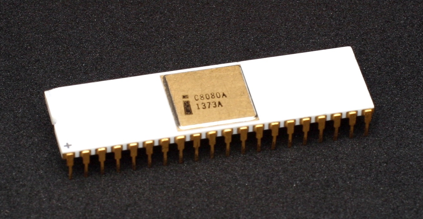
The registers, stack pointer, program counter, and flag bits can simply be represented as variables. The main work of simulating the processor is recreating its instruction set. The instruction set has 5 categories of instructions: data movement, arithmetic, logic, branching, and I/O. There are 248 instructions in total, with 8 of its possible 256 being no-ops. There are 79 unique operations shown below with their opcode mappings. Some operations take up multiple opcodes to account for each variation of the registers which the operation could be performed on. This is especially true for MOV, which takes up 63 opcodes as it can be used on any combination of the 7 registers or any register with any memory address, but not memory address to memory address (this is replaced with HLT).
Unique Operations and their Opcodes
0x00 - 0x30: NOP
0x01 - 0x31: LXI
0x02 - 0x32: STAX, STAX, SHLD, STA
0x03 - 0x33: INX
0x04 - 0x34, 0x0C - 0x3C: INR
0x05 - 0x35, 0x0D - 0x3D: DCR
0x06 - 0x36, 0x0E - 0x3E: MVI
0x07 - 0x37: RLC, RAL, DAA, STC
0x08 - 0x38: NOP
0x09 - 0x39: DAD
0x0A - 0x3A: LDAX, LDAX, LHLD, LDA
0x0B - 0x3B: DCX
0x0F - 0x3F: RRC, RAR, CMA, CMC
0x40 - 0x5F: MOV (with the exception of 0x76 which is HLT)
0x80 - 0x87: ADD
0x88 - 0x8F: ADC
0x90 - 0x97: SUB
0x98 - 0x9F: SBB
0xA0 - 0xA7: ANA
0xA8 - 0xAF: XRA
0xB0 - 0xB7: ORA
0xB8 - 0xBF: CMP
C0 - F0: RNZ, RNC, RPO, RP
C1 - F1: POP
C2 - F2: JNZ, JNC, JPO, JP
C3 - F3: JMP, OUT, XTHL, DI
C4 - F4: CNZ, CNC, CPO, CP
C5 - F5: PUSH
C6 - F6: ADI, SUI, ANI, ORI
C7 - F7: RST
C8 - F8: RZ, RC, RPE, RM
C9 - F9: RET, RET, PCHL, SPHL
CA - FA: JZ, JC, JPE, JM
CB - FB: JMP, IN, XCHG, EI
CC - FC: CZ, CC, CPE, CM
CD - FD: CALL
CE - FE: ACI, SBI, XRI, CPI
CF - FF: RST
Implementing the Instruction Set
To implement these 79 unique operatons, 78 functions must be written to carry them out (no need to make a function for no-op). Basic documentation for the instruction set, including cycle count, can be found at the back of the Intel 8080 Microcomputer Systems User's Manual. Extensive documentation on the instruction set can be found in the Intel 8080 Assembly Language Programming Manual. Both books were released in 1975. Most of the instructions can be implemented on a single line of code, with some taking 3 or 4 lines. The one outlier was the function for decimal adjust accumulator (DAA) at 7 lines.
DAA is a bit of an oddity. It is used when adding binary coded decimal (BCD) numbers. When storing BCD, the upper 4 bits and lower 4 bits of the register each represent one binary number (0 - 9). However, because binary addition is used when adding two BCD together, the 4 bit segments may hold values over 9 after an addition, making it no longer a BCD. To remedy this, DAA is used after the addition to convert the register back to holding a BCD. This is done by adding 6 to A if the lower 4 bits are greater than 9 or the auxillary carry flag is set, or adding 0x60 to A if the upper 4 bits are greater than 9 or if the regular carry flag is set. Additionally, the auxiliary carry flag is set if a carry happened from the lower 4 bits to the upper 4 bits when adding 6. All other flags are set as normal.
Implementing the External Hardware
With the 8080 emulating properly, most of the work is done. Still, it's not much use without some external hardware hooked up. As mentioned before, this application also emulates the hardware found in a basic Space Invaders arcade cabinet.
The cabinet has RAM and VRAM. RAM begins at address 0x2000, VRAM begins at address 0x2400, and RAM ends at 0x3FFF. It also has dedicated hardware for bit shifting, which can be represented by three variables: shift register 1, shift register 2, and shift offset, all of which need only be a byte large. Lastly, it has one more byte for control flags.
The cabinet has six controls: coin insertion, the 1 player start button, the 2 player start button, left and right movement, and the fire button. These can simply be mapped to keys on the keyboard. When pressed, they need to toggle the appropriate bit in the control flags byte. The coin is bit 1, the multiplayer start button is bit 2, the singleplayer start button is bit 3, fire is 5, left is bit 6, and right is bit 7.
Now, lets hook the machine up to the 8080 by using the IN and OUT instructions. These instructions interface with external hardware. IN reads a byte into the accumulator from the device number passed as the operand (0-255). OUT sends the contents of the accumulator to the device number passed as the operand.
The Space Invaders cabinet implements devices 0, 1, and 3 for the IN instruction. Device 1 simply sends 1, device 2 sends the control flags byte, and device 3 sends the result of shift registers 1 and 2 being combined (with 2 being the upper 4 bytes) and shifted right by 8 minus the shift offset. For the OUT instruction. Device 2 sets the shift offset equal to the first three recieved bits, and device 4 sets shift register one equal to shift register 2 and sets shift register 2 equal to the recieved byte.
Now everything has been implemented and the Space Invaders ROM will run successfully. The only thing left to do is convert the VRAM into something visible. The VRAM is simply a 224 by 256 array of bits, with each bit representing one pixel. Somewhat counterintuitively, 0 is for white and 1 is for black. The VRAM can be iterated over and converted into a texture which can then be rendered with OpenGL.